How the integration of Cloud PLM and CAD supports efficient product development
Engineers, designers, and CAD users often experience data chaos in their daily work: MCAD files (Mechanical Computer-Aided Design) can either be archived in a technical document management system or stored in the file system. While some ECAD systems (Electronic Computer-Aided Design) offer dedicated database solutions, there is still limited communication and interaction between the MCAD and ECAD worlds. The consequence? Mutual dependencies are not consistently represented in a single software. Although workflow management systems can provide good orientation about the current project phase, they are limited to merely providing links to documents without managing them reliably. This leads to data silos that complicate collaboration among design teams and slow down the entire product development process.
The integration of Cloud PLM and CAD solves this problem. PLM software connects CAD models with all other product-descriptive documents and data, breaking down silos and organizing the data chaos.
Find out how the integration of Cloud PLM and CAD leads to more efficient product development in this interview with Kai Ruhsert and Heiko Jesgarsz, Product Managers at CONTACT Software.
What is the advantage of PLM in the cloud?
KR: Product Lifecycle Management (PLM) allows companies to manage the entire lifecycle of a product, from the initial idea and development to production, distribution, and maintenance. Instead of installing PLM software locally, cloud-based PLM provides access via the internet. This not only leads to better scalability and increased security but also lower IT infrastructure costs. The integration of employees at any additional locations is simplified, making collaboration in global product development projects more efficient.
What benefits arise from the integration of Cloud PLM and CAD?
HJ: Many design teams need to collect, review, and assess product-related documents from various sources. Providing information to ERP systems or business partners further increases manual efforts. This is not only a challenging but also time-consuming task with significant potential for errors. In some cases, media discontinuities may occur, for example, when outdated information is recorded in Excel spreadsheets and passed on to downstream processes. The results are “data silos” which complicate information exchange and collaboration, causing unnecessary efforts.
Such shortcomings are particularly problematic when it comes to fulfilling documentation and process compliance due to high customer requirements or legal changes. Or when component manufacturers want to become system providers and the new customers demand an audit-proof documentation of the entire product development process. Without a PLM system, the necessary technical infrastructure for this is lacking.
The solution to this problem: managing all relevant data of the development process using PLM software, thereby creating a “single source of truth”. The PLM system not only links MCAD and ECAD models but also establishes a consistent cross-disciplinary database. This leads to high data consistency and transparency regarding the functional and structural relationships between electronics and mechanics.
The integration of Cloud PLM and CAD is particularly valuable for many companies as it simplifies collaboration and information exchange between design teams and other departments. This ultimately makes product development and manufacturing more efficient.
What solution does CONTACT Software offer to connect Cloud PLM and CAD data?
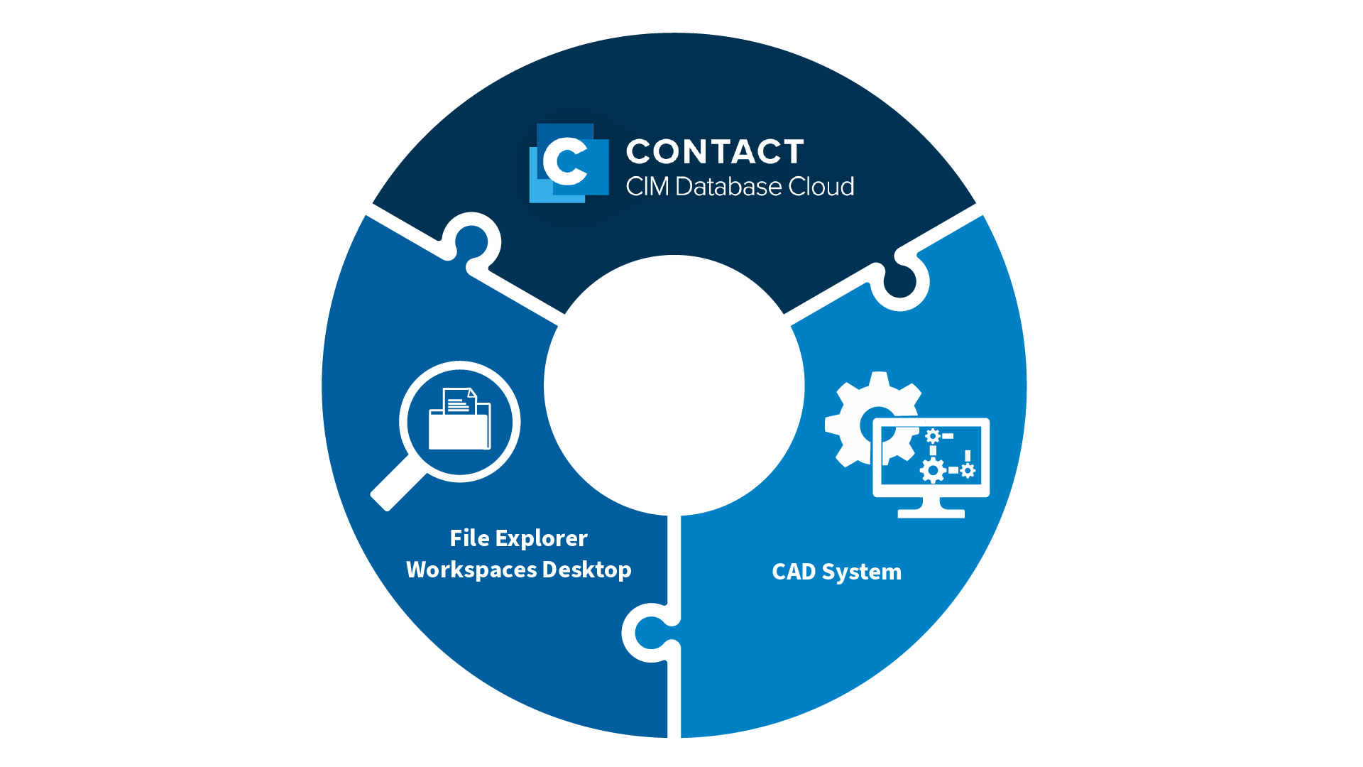
KR: The CONTACT Workspaces Desktop. This file explorer is a powerful tool for product data management. As a central platform, the Workspaces Desktop allows designers and CAD developers to customize their work environment, organize files, promote teamwork, and access essential tools for their work. It acts as the technical bridge between CAD systems and CONTACT Elements. Information seamlessly flows between these systems and product-relevant properties are securely stored in the CONTACT Elements platform.
The structures of documents in MCAD systems such as SOLIDWORKS, NX, Catia, and Creo are complex and require intelligent team data management. CONTACT’s Workspaces Desktop meets these requirements. It relieves designers from tedious routine tasks while ensuring a process-safe database. This is achieved through standard interfaces to leading MCAD and ECAD systems, along with the most powerful multi-CAD data management on the market. Additionally, the open architecture ensures seamless business processes with other IT systems like SAP.
In conjunction with CONTACT’s Cloud PLM system, CIM Database Cloud, the Workspaces Desktop allows to access all CAD data from anywhere at any time and to link it with all data along the entire product lifecycle.
Conclusion
The seamless integration of PLM and CAD is essential to avoid data silos. Cloud-based PLM software connects MCAD and ECAD models with all other product-relevant documents and data. This ensures access to identical data at any time and from anywhere. Using Cloud PLM with interfaces to CAD systems creates a fundamental prerequisite for efficient, cross-location collaboration between design teams.
The Cloud PLM system CIM Database Cloud integrates seamlessly with leading MCAD/ECAD systems. The CONTACT file explorer Workspaces Desktop allows users to connect all CAD documents with product lifecycle data and access them from anywhere.